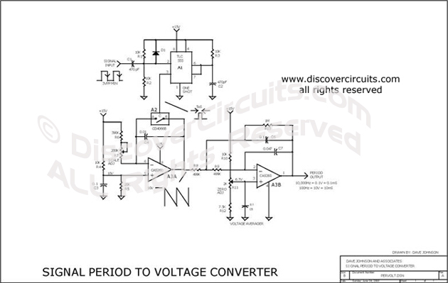
| A simple C-MOS timer IC (A1) is configured as a 5 microsecond one
shot. The resistors (R1) and (R2) bias the timer's input about 3 volts above the
triggering threshold. Since the timer fires only on the trailing edge of the input
waveform, the input signal does not have to have a symmetrical 50% duty cycle but it
does need a fast fall time. Standard TTL levels work fine. An operational Amplifier (A3A) is configured as a classical
integrator circuit. The resistors R6 and R7 in conjunction with the capacitor C4 define
the ramping rate. Biased at about 10 volts by the resistors R4 and R5 the integrator
ramps down from 10 volts to zero volts in 10 milliseconds.
The output of the 555 timer drives the control input of a C-MOS
analog switch (A2) connected across the integrator capacitor C4. During each trailing
edge of the input pulse waveform the 555 one shot fires causing the switch to reset the
integrator back to 10 volts. The average of the sawtooth waveform voltage produced at
the integrator's output is thus directly proportional to the time between the incoming
pulses. The variable resistor R7 is used to adjust the conversion scale and compensate
for component tolerances
The integrator's sawtooth waveform voltage is averaged using an
inverting low pass filter (A3B). The filter's components are selected to for a gain of 2
and a 5 hertz knee. The variable resistor R11 is used to set the zero reference voltage
(6.67v) so a short input period yields a near zero voltage. The operational Amplifier
(A3) was selected to provide near full supply rail swings and near ground level sensing
from a signal +15v supply.
With the component values shown the circuit produces a convenient 0.1
to 10v output for a 10,000Hz (0.1ms period) to 100Hz (10ms period) input signal. Other
scales are also possible using input frequency dividers or different integrator ramping
times.
This is a test circuit converts a square wave input signal into a voltage. But, the
voltage produced is proportional to the time between edges (period) of the signal,
not the frequency. The range is from 100uS to to 10mS, which produces a voltage from
100mV to 10 volts. Other scale factors are also possible. The circuit is powered
from single 15v supply and uses inexpensive parts. It is great when a signal's
period instead of its frequency needs to be monitored. |